After dusting off my work in progress MAME cabinet, following a hiatus of about 6 years, I’m determined to get the job completed. After a quick parts inventory I found I actually had most of the bits and pieces I need lying around the house, so set to work.
Cabinet painting

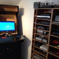
The cabinet itself was half primed, and so just need a quick rub down and the primer applied to the remaining bare MDF surfaces. I then applied the first coat of black latex-based paint that I had used for the control panel – you can see the effect after the first coat below. I used a small paint roller and applied a thin coat to ensure the finish was nice and even. I estimate 3 or 4 coats to do this properly, based on my experience with the control panel. It’s finally starting to look like a proper cabinet!
Control Panel Preparation
The control panel box had previously been primed and painted, and I had primed the control panel as well as drilling the cut-outs for the buttons and joysticks. The perspex overlay was also drilled, and so I only needed to paint the primed panel with black paint. This also took 4 coats to fully cover the white primer.
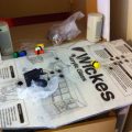
I had a mixture of Happ buttons from a kit I previously bought, but not enough of the right colours to complete the two colour red/blue look I wanted. I also needed some flat head bolts to hold the joysticks in place, so I ordered the components from Gremlin Solutions. I also took the opportunity to buy some plastic T-Molding to put around the panel and the exposed machine edges. I had already used a router to create the slot for the molding so this will just be pushed in place when the panel is complete.
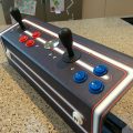
On receiving the remaining items I started to assemble, using the buttons themselves to hold the already drilled perspex in place. At this stage I realised the holes were a bit snug, and the paint had reduced the diameter of the holes even further, so a Stanley blade was used to chip away the paint, MDF and perspex. Fortunately the rough edges were hidden by the ridge around each button, but next time I will make the holes slightly bigger! Drilling the holes for the joystick bolts was slightly nerve wracking, as I had to drill directly through the perspex, and a crack at this stage would write off the whole panel, but all went well. Slow and steady and not too much pressure, and the drill just sailed through the perspex layer. The flat bolts also do a great job of holding the perspex in place, without snagging on your hand when using the joysticks.
I’m really pleased with the look of the panel, the perspex gives it a professional looking finish, and the buttons and joysticks feel just right – particularly with the micro switches in place, which give just the right level of resistance.
Wiring the control panel

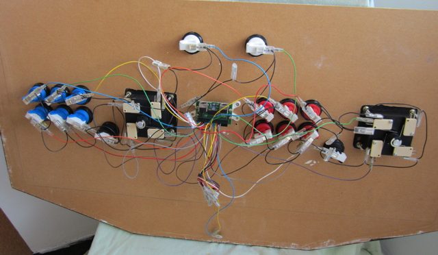
I already had an Ultimarc Minipac control panel interface, which I had previously bought on ebay as part of a kit. The Minipac came with a pre-wired harness, complete with spade connectors to link directly to the micro switches on each button and on the joysticks. Unfortunately my control panel layout was too big for the pre-wired harness, so some of the connections had to be extended using some additional wire acquired from Maplin. The black “common wire” which provides the power to each switch had some extra spade connections so I could stretch this to fit by just missing out a couple. All power to the PCB is through the keyboard interface to the PC, so no external power source is needed.
Although it looks complicated, the wiring process is relatively straightforward, as long as you take your time. It’s a bit if a birds nest at the moment but when I have tested the panel I will use cable ties to tidy up the harness.
Testing the MAME PC interface
With all the button and joystick switches connected, the panel was ready to test. I am using an old Dell Optimpex PC to run MAME, connected to a widescreen LCD monitor which I hope to mount on a swivel stand to allow horizontal and vertical display options without losing screen resolution. The PCB uses a PS2 type interface (the latest versions use USB connectors) so I had to buy a PS2 to PS2 cable on ebay. Powering on the PC, the PCB seemed to light up, but then the light went off. Using the setup software from Ultimarc, the PC did not seem to recognise the joystick movements or button presses, and a reboot did not help.
So I’m leaving this update on a slight cliffhanger (ooh the suspense), I think there may be a jumper missing from the PCB to tell it to

operate in PS2 mode, or it may be the Dell PC or Windows XP not recognising the PS2 connection. At least I have a great looking control panel, and worse case scenario I need to spend £30 on a new board with a USB link.
In my next update I’m hoping to have a working control panel, and finally have the MAME software running.